Design Tools
As my addiction has developed I have started to get more ambitious with my designs. No longer am I content with building electronics into pre made plexiglass cases (though I have made many). I am now more interested in re-purposing old wooden electrical equipment into clocks as well as producing my own designs.


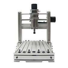
This is the style of router that I have though mine has more wood dust!
Woodwork
Woodwork is something that I have managed to avoid ever since making a dovetailed box in woodwork lessons at school. Consequently I have no skills, experience oR confidence in this area. My approach has been to base my creations of wood that I can cut with machines, namely my very small CNC Router. This has actually turned out to be quite a success and as I progress I have learnt which techniques work well and which ones don’t!
My router is one of those which are popular on ebay and is known as a 3040 (300mm x 400mm) cutting area. It came with everything needed to get going including software. The software will take your Gcode and drive the router – but you need to come up with the Gcode in the first place. Initially I used something called ‘SimpleCNC’ which produced Gcode for individual shapes and cuts as required and this was quite successful.
After a while I realised that for more complex designs I was going to have to use something a little more sophisticated. I ended up with Solid Edge 2019 from Siemens. This is a fairly fully loaded 2D drafting application which has all the tools that I will ever need to make parts for routing. That’s all good but Solid Edge still doesn’t quite cut it (see what I did there?) when it comes to making GCode – simply put – it doesn’t do that. I then discovered CamBam which will take a DXF file (which Solid Edge can make) and will allow the creation of all the Gcode that you will need to make the cuts on the router.
The basic workflow is: Design all required parts in Solid Edge and save a copy of the file in DXF format. Load the DXF in to CamBam and for each part required, create the toolpaths and Gcode files. Load the CNC Driver software (USBCNC for me) and use that to process each Gcode file to make the cuts on the router. Job done!
Once you have got your head around how each application works then it is fairly straight forward though I did find learning Solid Edge a bit tough to start with. There are plenty of online tutorials to help. For the enthusiast – Sold Edge and CamBam are both free – which is nice.
Electronics
As my projects progress, I have developed a need to make Printed Circuit Boards and after taking much advice and listening to other people who have taken a similar journey I decided to have a go with KiCad. It was a steep learning curve (and I’m still only at the start) but I have managed to make a couple of PCB’s which turned out alright (absolutely NOTHING complex) but it’s a start.
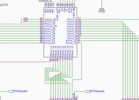
After some success with KiCad I was introduced to EasyEDA which is an online design environment which allows on-line creation of designs and PCB layouts.
I found it easy to use and easy to generate ‘PCB Footprints’ for which is extremely useful as i have found that I regularly use components for which no footprint exists.
I should point out that this facility exists in most if not all other applications – I just found it easier in EasyEDA.
I have used EasyEDA to make over 35 different boards now and love it. I would recommend it to anyone who fancies having a go.
I get boards producted at jlcpcb.com (who probably own EasyEDA) and have been happy with quality and price of the delivered product.

Like KiCad, EasyEDA has more than enough features for my needs

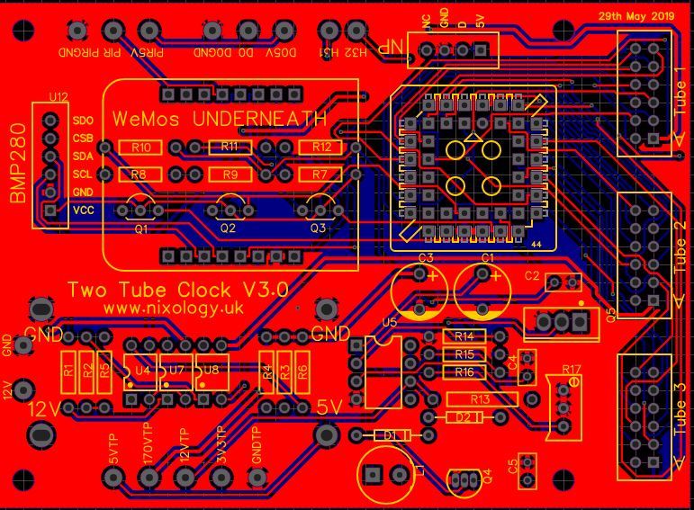
This is typical of the kind of board that I turn out – this particular one includes a prototype HV power supply , I read all the design considerations for the circuit after laying out this particular board, another version coming soon I suspect!